Grouped into five capability areas. Each service can be commissioned on its own, or chained into a complete process from principle assessment and design to manufacturing and acceptance testing. We are open to all service scopes, and requests not listed here are welcome too.
1. Optoelectronic integration and infrared imaging
Whether a system will work is mostly decided at the selection stage. The value of this part is confirming that the method itself is right before you invest in hardware.
Incoming radiation → optical system → focal plane array
01
Optoelectronic and electronic system integration consulting
Consulting on principles and system design. For your measurement goal, we clarify which optical and electronic components are needed, the constraints between them, and the architecture that is feasible within your budget.
PrinciplesSystem designFeasibility
02
Optoelectronic and electronic system integration custom design
System integration planning, design and interface design. We turn the architecture into a workable design, including interface definitions across optics, mechanics and electronics, signal specifications and assembly sequence.
Integration planningInterface designCustom design
03
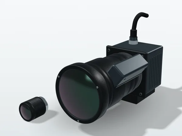
Infrared imaging (SWIR/MWIR/LWIR) principles and consulting
Understand the imaging principles and how to choose the right waveband and lens focal length. "Seeing heat" at room temperature and in a high-temperature process calls for completely different bands; choose the wrong band and every later effort is discounted. The detailed criteria are in our band reference table.
Waveband selectionFocal lengthSWIRMWIRLWIR
04
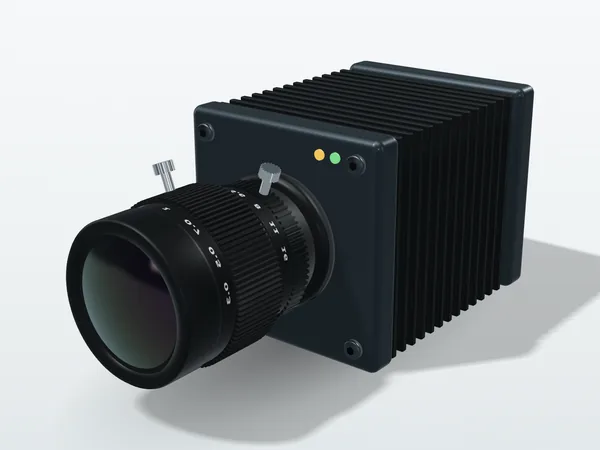
Infrared imaging system integration and testing
System integration planning, interface design and early validation. We connect the camera, lens, triggering and data acquisition into a system that runs reliably, and complete early validation before production.
System integrationEarly validationData acquisition
05
Infrared camera module testing
Custom test validation of camera modules. We define test items and acceptance thresholds for your application instead of copying generic numbers from the datasheet.
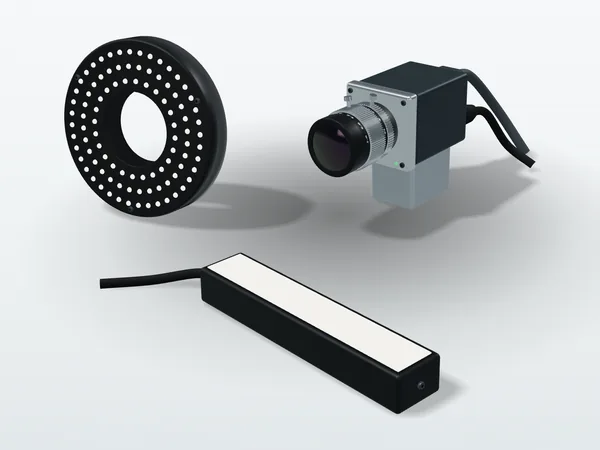
Setting up vision inspection stations on the line: camera and lens selection, lighting method, resolution and depth-of-field calculation, and trigger synchronization between image capture and motion control. We work back from "how small a defect must be seen" to the specification, instead of buying a camera first and then trying to make it see. The method and examples are on our industrial automation integration page; what to check before adoption is covered in Five Questions to Ask Before Adopting AOI.
Camera selectionLenses and lightingResolutionTrigger sync
2. EO/IR payloads and industrial automation
Integrating several sensors into a payload that works in the real environment, whether it flies on a gimbal or sits on a machine taking measurements, and bringing measurement capability onto the production line.
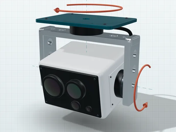
The visible and infrared cameras are aimed at the same point, but the laser rangefinder is off by a few milliradians: the image shows the target locked, while the reported distance is to the wall beside it. This error is invisible at short laboratory distances and grows at real operating ranges, which is why boresight calibration and gimbal accuracy testing must be done together (3D illustration; the error is exaggerated and not to scale).
07
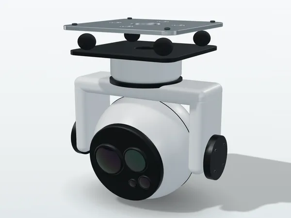
EO/IR/LRF payload design, testing and UAV flight controller integration
Custom multi-sensor EO/IR payloads for fixed, vehicle and UAV mounting. Boresight alignment and synchronization between the visible camera, infrared camera and laser rangefinder are a common source of problems in such payloads, so we handle them together with optical and mechanical selection: working back from the mission target and operating range to ground sample distance and focal length, designing the counterweights and BLDC direct-drive control of the stabilized gimbal, compensating parallax between the two image channels, and planning image tests and gimbal accuracy tests.
UAV projects also include flight controller integration: interfacing with PX4 or ArduPilot over MAVLink for gimbal pointing, target tracking and ground coordinate calculation.
For a gimbal designed for your platform and mission, commission a custom EO/IR gimbal: from mechanics, motors and encoders and stabilization control to sensor integration, boresight calibration and prototype testing (origin: Taiwan).
EO/IR dual sensorTri-sensor with LRFStabilized gimbalCustom gimbalBoresightImage testingMAVLinkGeolocation
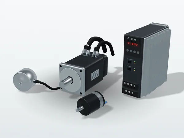
Industrial machine integration, motor control and automation GUIs. A measurement station should not only measure but also capture, judge and record automatically within the line cycle time. AC servo and BLDC selection and tuning, multi-axis synchronization, and the trigger timing between motion and image capture are all handled here.
The final accuracy of an optical system is often limited not by the lens but by the structural part that holds it and the cable attached to it.
09
Precision industrial mechanical design
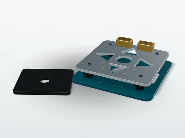
Precision mechanical blueprint design, including tolerance allocation and opto-mechanical interface definitions, so that optical elements stay in their design positions after assembly and temperature changes. The full method is in Tolerance Allocation.
Precision machining. From drawings to physical parts, including the specification of materials and surface treatments.
Precision machiningMaterialsSurface treatment
11
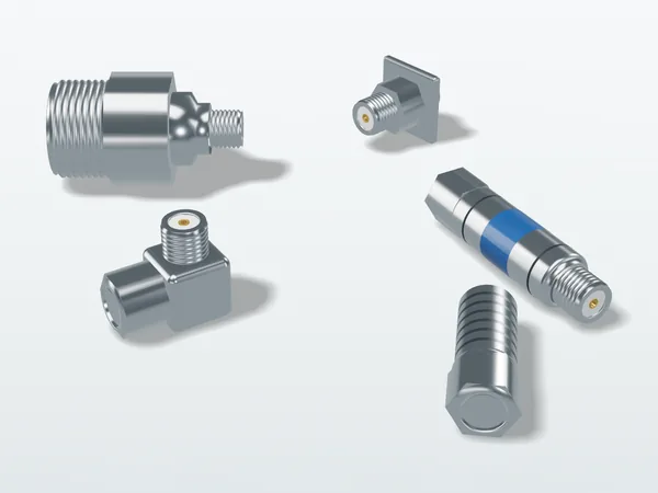
Industrial and military-grade connector selection and custom test cables
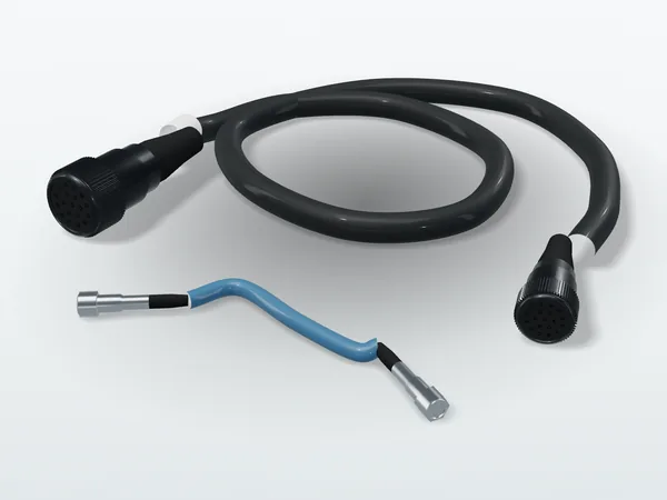
We help select environmentally rugged connectors, provide integration specifications and build custom test cables. Different temperature, vibration, salt fog and EMI conditions call for completely different connectors and wire. What to include in a quote request is on the test cable assemblies page.
RF needs beyond optoelectronics, and turning "something feels off" into a set of numbers that can be accepted.
12
Custom passive microwave component design
Passive microwave component design and performance simulation. Simulation confirms where the performance will land before fabrication or tooling.
Component designPerformance simulation
13
Custom passive microwave component manufacturing
Passive microwave component manufacturing. Design and manufacturing are handled by the same party, so the specification is not distorted in handover.
ManufacturingOne-stop
14
Custom data analysis
You provide the direction, and we turn it into performance test items. This is where many projects really start: defining a vague quality concern as test items that can be measured repeatedly and have threshold values.
Test definitionData analysisAcceptance thresholds
5. C2ISR integration
Electro-optical sensing, edge computing, data links and the operating picture designed as one chain: first ask what the command post needs to know, how accurately and how fast, then derive the specification of every sensor node and interface from that.
15
C2ISR system architecture and interface design
Measurable specifications defined from the mission: range, target geolocation error, end-to-end latency, link bandwidth and continuous operating hours. We select sensors and computing platforms, define the system architecture, time synchronization and coordinate conventions, and write the Interface Control Document (ICD) so sensor data enters your existing C2 or surveillance platform in a format it understands. Geolocation error and latency are broken into item-by-item budgets to find the dominant terms before deciding where the money goes.
C2ISR system integration, operating picture and verification
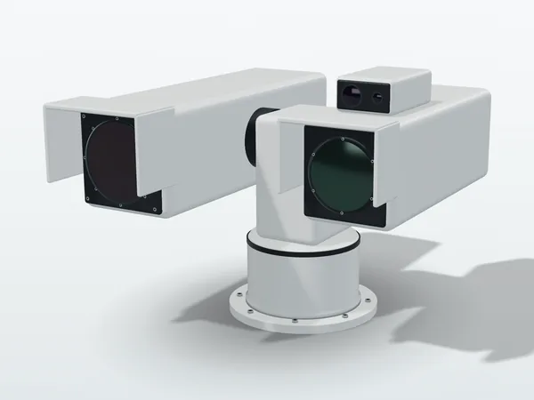
Integration of EO/IR/LRF sensor nodes, stabilized gimbals and long-range pan-tilt systems; edge computing at the sensor for AI detection, tracking and target geolocation; link integration for video streaming, KLV metadata, tracks and alerts; and common operational picture (COP) and console software where clicking a track slews the gimbal to it (slew-to-cue). Logic and interfaces are tested in the lab with hardware-in-the-loop (HIL) simulation first, then latency, geolocation error and detection rate are accepted in the field.
Original illustration, not a product photo. Actual appearance varies by model.
Not sure where to start?
Tell us about your application, the object under test and the problem you want to solve; we will first work out which method it calls for, then discuss scope and schedule.