The specifications of an off-the-shelf gimbal are measured under the manufacturer's test conditions. Once it is mounted on your airframe, fitted with the focal length you need and flown at your real mission altitude, many of those numbers have to be confirmed again. What we do is the part that works back from the mission to the specification: first we ask how large an object you need to see, from what height and in how much detail, and only then decide how the sensors, focal length, gimbal and flight controller interface fit together.
Video: UAV EO/IR for civilian use
A video we made showing how one UAV EO/IR payload is used by day and by night in four civilian missions: mountain search and rescue, flood survey, power line inspection and bridge inspection.
The four missions share one pattern. By day, the sun heats the ground, roofs and structures, so thermal contrast is low and the EO zoom camera does most of the confirming. At night, the background cools, the thermal camera readily finds people and hot spots, and a searchlight or onboard light lets the EO camera confirm. The thermal contrast of the same defect can even reverse between day and night (the delaminated areas on the bridge).
Mission
Day
Night
Mountain search and rescue
Grid search at about 90 m. The sun has heated the ground, so a person shows little contrast in the thermal image; the EO zoom camera confirms
Descends to about 60 m and searches mainly in thermal to find body heat, then turns on the searchlight so the EO camera can confirm, and guides the rescue team
Flood survey
Orthophoto mapping; the EO camera finds people stranded on roofs. Roofs are about 45 °C, so thermal contrast is low
In a village without power, roofs have cooled to about 5 °C and body heat stands out clearly; after confirming with the searchlight, the UAV guides the rescue boat
Power line inspection
Flies along the line about 27 m from the conductors. Sunlight masks the temperature rise at joints (about 48 °C against 38 °C)
With no solar heating, a joint at 78 °C against 11 °C is clearly visible; tree clearance to the conductors is also checked
Bridge inspection
Scans the side, then flies under the bridge (switching to visual positioning); the EO camera finds cracks on the girder underside. Delaminated areas run warm in the sun
Uses the onboard light for illumination; at night delaminated areas instead run 2.6 °C cooler, demonstrating the day-night reversal of thermal contrast
Flight heights, distances and temperatures in the table are the demonstration values shown in the video; real missions vary with the site, weather and load. Night flights need prior approval under Taiwan's drone regulations (see section 7).
1. Four capabilities, one chain
These four are best not contracted out separately. Change the focal length once, and the gimbal's inertia, the natural frequency of the vibration isolation, the image data rate and the geolocation error budget all change at the same time. When they are done separately, a common outcome is four parts that each pass on their own but do not work together.
Optical design and waveband selection
Selection of lenses, filters, windows and coatings, the common-aperture layout of EO and IR, and the thermal defocus that infrared lenses always have to deal with. Focal length is worked back from "how fine you need to see", not picked from a catalog.
Stabilized gimbal mechanics and servo control
Mechanical design of two- or three-axis gimbals, counterweighting and lightweighting, natural frequency planning for the isolation mounts, and torque and control loops for BLDC direct drive. Stability is not bought; it is balanced in.
Dual-sensor image processing and boards
Boresight alignment, parallax compensation and image fusion between EO and IR, the latency budget for real-time streaming and compression, and interfacing and firmware for embedded computing boards (MCU/FPGA).
Flight controller integration and target geolocation
Gimbal pointing and mission waypoints over MAVLink with PX4 or ArduPilot, converting a point in the image into ground coordinates, and breaking the error budget down for you item by item.
The specification chain. The example is "identifying a person at the legal 400 ft ceiling (able to make out details such as clothing and handheld objects)": the critical dimension of a person is taken as 0.75 m, and identification under the Johnson criteria needs 6.4 line pairs, that is 12.8 pixels across it, so the ground sample distance (GSD) must not exceed 58.6 mm; dividing by the 122 m altitude gives an instantaneous field of view of 480 µrad; dividing the 12 µm pixel pitch of an uncooled longwave infrared core by this instantaneous field of view gives a focal length of 25 mm. Change any link and everything after it changes with it.
2. Calculate the specification first, then talk about models
Below, a common dual-sensor configuration serves as the baseline, with all the numbers laid out. For EO we take a 1/1.8-inch CMOS sensor (3096 × 2080, 2.4 µm pixels, 7.43 × 4.99 mm active area); for IR an uncooled microbolometer (640 × 512, 12 µm pixels, 7.68 × 6.14 mm active area, 8–14 µm). Altitude is always 122 m, the regulatory 400 ft ceiling.
Sensor
Focal length
Horizontal FOV
IFOV
GSD at 122 m
Ground coverage width
EO visible
16 mm
26.1°
150 µrad
18.3 mm
56.7 m
EO visible
25 mm
16.9°
96 µrad
11.7 mm
36.3 m
IR longwave infrared
13 mm
32.9°
923 µrad
113 mm
72.1 m
IR longwave infrared
19 mm
22.9°
632 µrad
77.1 mm
49.3 m
IR longwave infrared
25 mm
17.5°
480 µrad
58.6 mm
37.5 m
Table 1: IFOV = pixel pitch ÷ focal length; GSD = IFOV × altitude; ground coverage width = active area width ÷ focal length × altitude. The horizontal field of view is calculated with the pinhole model 2·arctan(D/2f), whose error is negligible over this focal length range; wide-angle lenses (for example below 5 mm) have significant distortion, so the actual field of view is larger than the formula gives and the manufacturer's measured value must be used.
Comparing the GSD above with the interpretation thresholds makes the feasible focal length range clear. With a person as the target and a critical dimension of 0.75 m, the Johnson criteria require 1.0 line pair (2 pixels) for detection, 4.0 line pairs (8 pixels) for recognition and 6.4 line pairs (12.8 pixels) for identification; converted to GSD thresholds, these are 375 mm, 93.8 mm and 58.6 mm.
Task
GSD threshold
Shortest IR focal length in Table 1 that meets it (122 m)
Cost
Detection: knowing there is a person there
≤ 375 mm
IR 13 mm (GSD 113 mm, ample margin)
Widest coverage, fast single pass
Recognition: telling it is a person, not an animal
≤ 93.8 mm
IR 19 mm (GSD 77.1 mm)
Coverage width drops to 49.3 m
Identification: distinguishing detailed differences between targets of the same class (such as clothing or handheld objects)
≤ 58.6 mm
IR 25 mm (GSD 58.6 mm)
Exactly at the threshold, no margin
Table 2: the Johnson criteria give the minimum resolution for a 50 % probability of correct interpretation, and assume sufficient contrast between target and background. When the background temperature is close to the target (for example during thermal crossover around dawn and dusk), when the air is humid, or when the target is hidden by vegetation, real performance is worse, so "exactly at the threshold" should not be treated as a passing design. To identify reliably at 122 m, in practice you should move to focal lengths of 35 mm or longer, or fly lower.
3. Gimbal: stability comes from balancing
A gimbal has two completely different kinds of error, and datasheets often mix them together: pointing error is "the gimbal thinks it is pointing here but is actually pointing there", which affects target geolocation; jitter is "the image is shaking", which affects image quality and whether the tracker can hold a lock. The first is solved by calibration and attitude measurement, the second by mechanics and control.
Counterweighting: a five-millimeter offset becomes two pixels
The disturbance torque about a gimbal axis (the bearings take only radial loads, so this torque has to be countered by the motor) equals payload mass × airframe acceleration × offset of the center of gravity from the axis. With a 0.35 kg payload and a lateral airframe acceleration of 3 m/s² (a typical magnitude when a multirotor stops abruptly): a 0.5 mm offset gives a disturbance torque of 0.525 mN·m; a 5 mm offset gives 5.25 mN·m.
Dividing the torque by the payload's moment of inertia about that axis (taken as 3.5 × 10⁻⁴ kg·m²) gives angular accelerations of 1.5 rad/s² and 15 rad/s². The control loop takes about 5 ms to pull it back, and the angular deviation accumulated in that time is 18.8 µrad and 188 µrad. Compared with the 96 µrad IFOV of the EO 25 mm lens, balancing to within 0.5 mm means 0.2 pixel, while 5 mm means the image jumps by 2 pixels. Same motor, same algorithm; the only difference is whether the center of gravity was brought onto the axis.
Vibration isolation: a misplaced natural frequency amplifies vibration
The main vibration source on a multirotor is the fundamental frequency of propeller rotation: 6000 rpm is 100 Hz. An isolation mount is a spring-mass system, and it only starts isolating when the excitation frequency is above √2 times the natural frequency; below that ratio it actually amplifies vibration.
Vibration transmissibility at a damping ratio of 0.2. Mount a 0.6 kg gimbal assembly on isolators with a 25 Hz natural frequency (four mounts sharing the load, total stiffness 14.8 N/mm, static deflection 0.40 mm at 1 g), and the 100 Hz propeller frequency falls at a ratio of 4, with transmissibility 0.125 and 87 % vibration reduction. But note the amplification zone on the left: during takeoff, landing and at low rotor speeds, the propeller frequency sweeps up through the 25 Hz resonance, and at that moment vibration is amplified about 2.7 times. This is why many gimbals are "steady in flight but shake badly before takeoff", and why isolation material cannot be chosen for softness alone: damping must be considered as well. Higher damping sacrifices isolation at high frequencies, so the two have to be traded off together.
Drive: why BLDC direct drive
A gimbal moves over a small range, at low speed, and must move smoothly. This is exactly where gears perform worst, because backlash turns directly into pointing jumps at every reversal. So most stabilized gimbals use BLDC direct drive, relying on a high pole count for smooth torque at low speed and keeping cogging torque to a minimum. The selection logic is the same as for production-line servos, only with much smaller inertia and torque; the full method is in How to Choose a Servo Motor: Three Numbers That Decide Whether a Mechanism Moves Accurately. Whether angle feedback should use an optical, magnetic or capacitive encoder, and why a magnetic solution next to a direct-drive motor needs extra handling of stray magnetic fields, is covered in section 2.3, Angle feedback, on the industrial automation integration page.
For a gimbal designed around your platform and mission, see custom EO/IR gimbals (origin: Taiwan); if an off-the-shelf gimbal is enough, see EO/IR gimbals.
4. Dual sensors: two cameras align at only one distance
EO identifies and IR finds: that is the division of labor in a dual-sensor payload. But the two cameras have two separate entrance pupils with a baseline between them, so physically they cannot coincide at every distance.
For two cameras with a 40 mm baseline pointed at the same point, the parallax angle is the baseline divided by the distance. Aligning them at 122 m during calibration removes the parallax at that distance, but only at that one distance. When you fly in to 30 m for a close look, the residual is 40 mm × (1/30 m − 1/122 m) = 1.01 mrad, which is 10.5 pixels in 96 µrad EO pixels and 2.09 pixels in the 480 µrad pixels of the IR 25 mm lens. Fly out to 500 m instead and the residual becomes 0.25 mrad in the opposite direction, about 2.6 EO pixels.
Target distance
Parallax angle
Residual after calibration at 122 m
EO pixel offset
IR pixel offset
30 m
1.333 mrad
1.01 mrad
10.5 px
2.09 px
122 m
0.328 mrad
0 (calibrated)
0 px
0 px
500 m
0.080 mrad
−0.25 mrad
2.58 px (opposite)
0.52 px (opposite)
Table 3: parallax residual with a 40 mm baseline and alignment done at 122 m (residual = baseline × (1/distance − 1/calibration distance)). This is caused by geometry and has nothing to do with how well the alignment was done; alignment can only zero one distance. If a picture-in-picture or overlay display does not take distance into account, at close range the hot spot gets marked beside the object, which can mislead decisions at a fire scene. In practice, slant range is estimated from the gimbal depression angle and altitude, or a laser rangefinder is added, for real-time distance-dependent offset compensation.
Thermal defocus in infrared lenses is worse than you think
Germanium is the most common lens material for longwave infrared, with a refractive index of 4.0032 (at 10 µm) and a thermal expansion coefficient of 6 ppm/K, but its thermo-optic coefficient is as high as 396 ppm/K, almost two orders of magnitude higher than ordinary optical glass. The temperature coefficient of focal length for a single germanium lens is 6 − 396 ÷ (4.0032 − 1) = −126 ppm/K.
For a 25 mm lens and a 40 K temperature change (for example a housing that has baked in the sun on the ground and is then cooled by airflow after takeoff, or a payload whose required operating temperature range itself spans several tens of degrees; the 122 m altitude difference alone brings only about 1 °C of air temperature change), the focal length drifts by 126 µm. With f/1.0 and a permissible blur circle of one 12 µm pixel, the depth of focus is only ±12 µm: the drift is more than ten times the depth of focus. Worse, over the same 40 K an aluminum housing pushes the detector back by 23 µm, in the opposite direction to the focal shift, for a total defocus of nearly 150 µm. So infrared lenses with a wide operating temperature range must be athermalized (or use active focus compensation), with high-expansion spacers that move the lens group, or a hybrid design of germanium and chalcogenide glass whose temperature coefficients cancel each other out. A payload that skips this step slowly goes soft during flight, and room-temperature ground tests often fail to reveal it.
Incidentally, the Airy disk diameter at f/1.0 and a 10 µm wavelength is 2.44 × 10 × 1.0 = 24.4 µm, exactly two pixels. Longwave infrared lenses are almost always made at f/1.0 to f/1.4, mainly because the NETD of an uncooled detector worsens roughly with the square of the f-number: stop down by one stop and thermal sensitivity is halved. Add the fact that diffraction already takes up two pixels, and there is no room to trade aperture for depth of field. For coatings, see Optical Coatings 101.
5. Flight controller integration and target geolocation
The payload must be commandable from mission planning, and must be able to convert what it sees into ground coordinates and report them. This part is a software interface, and it is also an error budget.
Interface: the MAVLink gimbal protocol
Both PX4 and ArduPilot support MAVLink Gimbal Protocol v2. The protocol splits the gimbal into two roles: the Gimbal Device is the hardware itself, reporting GIMBAL_DEVICE_INFORMATION and GIMBAL_DEVICE_ATTITUDE_STATUS; the Gimbal Manager arbitrates commands from the ground station, mission scripts and the companion computer, and is the only party on the network allowed to command the device directly. Pointing control from the mission side uses MAV_CMD_DO_GIMBAL_MANAGER_PITCHYAW (angles) or MAV_CMD_DO_SET_ROI_LOCATION (ground coordinates, which the Gimbal Manager converts into angles and keeps pointing at).
Getting the roles straight matters: a common reason for a gimbal that "wanders" is not a broken control loop, but the ground station and onboard software issuing commands at the same time with no Gimbal Manager in the system to arbitrate.
Geolocation: with magnetometer heading, the error comes mainly from heading
Converting a point in the image into ground coordinates uses airframe position + airframe attitude + gimbal angles + slant range. When angular errors are projected onto the ground, the magnification depends on direction: heading error causes a lateral offset, magnified by the horizontal distance; error in the depression direction causes a longitudinal offset, magnified by slant range ÷ sin(depression angle). Taking an altitude of 122 m and a gimbal depression angle of 45° as an example (horizontal distance 122 m, slant range 172.5 m, longitudinal magnification about 244 m), we first list each angular error, then project by direction and combine by root sum of squares (RSS). Airframe attitude, boresight residual and encoder error are all conservatively treated as lying in the depression direction, and the ground is assumed flat with known target height; with a laser rangefinder, the longitudinal error in this geometry can be roughly halved.
Angular error budget for target geolocation. A gimbal encoder at 0.05° looks impressive, but that is only 0.9 mrad; the 2° magnetometer heading error alone is 34.9 mrad, 97.5 % of the sum of squared angular errors, and still about 90 % after projection onto the ground. In this example, spending money on a better encoder barely improves geolocation accuracy; replacing the magnetometer with dual-antenna satellite heading brings the ground error down from about 4.5 m to about 1.4 m. Once dual antennas are used, airframe attitude becomes the dominant term. This is why the payload specification has to be considered together with the vehicle: looking at the payload alone, it is easy to chase the wrong bottleneck.
The accuracy of dual-antenna heading depends on baseline length. The relative position of the two antennas is solved from carrier phase, and the position residual divided by the baseline length is the angular error, so angular error is roughly inversely proportional to baseline length: halve the baseline and heading error roughly doubles. The 0.2° in the chart above is an assumed value for this example and must be recalculated for the actual baseline and receiver. In practice the two antennas are spread as far apart as possible, at opposite ends of the arms; the Inertial Sense documentation recommends a baseline of at least 0.25 m for multi-band solutions, and shorter baselines still work but with reduced stability. Also remember that the position error of satellite positioning itself adds directly: standalone horizontal error is generally around 1–2 m (a common specification is about 1.5 m CEP), while RTK reaches centimeter level. In the magnetometer example, this roughly 1.5 m position error is swamped by the 4.5 m angular error; with dual antennas it is of the same order as the 1.4 m angular error, and the two combined come to about 2 m. This still leaves out the error in altitude itself: at a 45° depression angle, every 1 m of error in height above ground gives about 1 m of longitudinal error (a factor of 1 ÷ tan(depression angle)), so barometric altitude drift or terrain relief adds directly. The error budget has to be recalculated as a whole, not one item at a time.
Dual-antenna baseline recommendation from the Inertial Sense documentation, "RTK Compassing": https://docs.inertialsense.com/user-manual/gnss/rtk_compassing/
Guidance: letting the aircraft follow the target
Once the interface is connected, there is another layer: feeding image-side information back to the flight controller. The tracker locks onto a target in the image, calculates its angular offset from the center, and converts it into gimbal rate commands that bring it back to center; at the same time, the computed target coordinates are sent to the Gimbal Manager with MAV_CMD_DO_SET_ROI_LOCATION, so the gimbal keeps pointing at that spot while the aircraft moves. ROI handles pointing only and does not plan a flight path; to fly around the target you need a separate orbit command (such as MAV_CMD_DO_ORBIT, supported by PX4) or waypoints generated by the companion computer. The latency budget here is the same kind of problem as synchronizing image capture with motion on a production line: image processing that is 100 ms slower means 1 m of lag at 10 m/s. For how to handle it, see the section on how synchronization error turns into position error in EtherCAT and Multi-Axis Synchronization: Why Distributed Clocks Matter.
6. Three domains, three different specifications
With the same EO/IR dual sensor, different missions call for optimizing completely opposite things.
01
Firefighting and search and rescue
Priority: coverage and detection speed. Sweep for thermal anomalies first with wide-field IR, then confirm with EO. Longwave infrared sees through smoke, because smoke particles are much smaller than the 10 µm wavelength and scatter weakly, but it cannot see through condensed water mist or glass: the droplets and water curtains produced by firefighting streams block longwave infrared, so hot spots are hidden or the whole scene turns hazy.
Fire temperatures far exceed body temperature, so high and low gain modes are needed, or everything near the fire saturates
Night flights are prohibited by law; government agencies, schools or legal entities must first apply for permission from the Civil Aviation Administration
Ground speed must stay below the smear threshold, or a fast sweep is a useless sweep
02
Power line, bridge and wind turbine inspection
Priority: resolution and repeatability. What you are looking for is abnormal temperature rise and structural cracks, and the judgment relies on relative temperature differences between points on the same line, not absolute temperature, because the absolute value is affected by emissivity, reflected background and distance.
Porcelain insulators reflect the sky and the sun and can look like hot spots, so recheck from another angle
Flight paths must be repeatable so that images can be compared point by point with the previous survey
Crack interpretation usually depends on EO resolution; IR only marks out suspicious areas first
03
Public-sector surveillance (ISR)
Priority: endurance and geolocation accuracy. In long observations, every extra 100 g and every extra 1 W of payload translates directly into lost flight time; and the reported coordinates must let ground teams go straight there, so the error budget has to reach meter level.
Uncooled longwave infrared beats cooled cameras on power consumption and instant start-up, at the cost of sensitivity and range
With magnetometer heading, heading accuracy dominates geolocation error and takes priority over the gimbal encoder
Latency and encryption of the video link must be defined together with the requirements of the command structure
For the whole chain from sensing and edge computing to data links and the operating picture at the command post, see C2ISR integration.
7. Regulations directly determine the specification
Taiwan's rules for remotely piloted aircraft are set out in the drone chapter of the Civil Aviation Act and in the Regulations Governing the Management of Remotely Piloted Aircraft. The following provisions directly change the design conditions of the payload; they are not just a matter of compliance paperwork.
Rule
Impact on payload design
Flight altitude must not exceed 400 ft (about 122 m) above ground or water
With altitude capped, the only ways to raise the interpretation level are a longer focal length, a sensor with a smaller pixel pitch, or flying lower; and a longer focal length brings narrower coverage and stricter stability requirements
Must be operated within visual line of sight, with no aids other than corrective lenses to extend the distance
The design limit for operating range follows visual line of sight; extended visual line of sight operations are limited to a 900 m radius around the operator and 400 ft altitude, and require a visual observer
Flight is prohibited from sunset to sunrise
Missions such as night search and rescue need permission first, and the payload's low-light specification should match the time windows actually approved
No dropping or spraying of any objects, and no carrying of dangerous goods on the published list
Dropping, spraying or carrying such goods requires prior approval from the Civil Aeronautics Administration, applied for by a government agency, school or juridical person; plan the release mechanism and the application together
No operation over crowds or outdoor assemblies and parades; no controlling two or more aircraft at the same time
Flight paths and observation geometry in urban areas are restricted, which feeds back into the design of field of view and depression angle
Aircraft owned by individuals with a maximum takeoff weight of 250 g or more must be registered; those owned by government agencies, schools or legal entities must always be registered, and operators must hold an operator certificate
The total weight budget (including payload) is a threshold for administrative classification, not just an endurance question
Table 4: compiled from the Civil Aviation Act and the Regulations Governing the Management of Remotely Piloted Aircraft (for the scope of extended visual line of sight, see Article 28 of the Regulations). After applying to the Civil Aviation Administration for permission under Article 32 of the Regulations, government agencies, schools or legal entities may carry out some restricted operations; night missions and missions beyond the extended visual line of sight range usually take this route. Provisions and review procedures are revised from time to time, so please check the latest announcements from the Civil Aviation Administration before a project starts; we will also confirm them together at the specification meeting.
8. How a project starts
The most efficient starting point is not a specification document, but the answers to three questions.
Q1
How large an object, seen from how high?
Give us the actual size of the target and the mission altitude, and tell us whether you need to "know something is there" or "recognize what it is". Once these two numbers are known, the feasible range of focal lengths and sensors narrows to two or three options.
Q2
What is the vehicle, and how much weight and power are left?
The model, maximum takeoff weight, current payload margin and power supply specification, and whether the flight controller runs PX4 or ArduPilot, and which version. This determines the size class of the gimbal and how it interfaces.
Q3
Who receives the results, and in what form?
Real-time interpretation on site, a report afterwards, or input into an existing information system? Whether images need coordinates and whether raw radiometric data must be kept have a large effect on board and storage specifications.
Once the three questions are answered, you can also commission the UAV Payload Specification package directly: after receiving your requirements we provide a fixed-price quotation, and deliver a specification proposal and error budget.
Related products
Items related to this page that we also supply, each with specifications and selection notes.
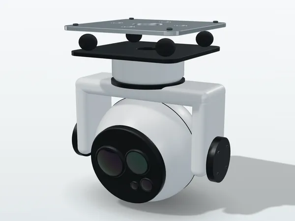
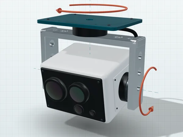
Original illustration, not a product photo. Actual appearance varies by model.
Give us the mission conditions, and we will calculate a specification first
You do not need a specification document first. Tell us the altitude, the target and the vehicle, and we will send back a specification proposal and error budget like the one above, in which you can check every number yourself.
How a few millimeters of counterweight offset turn into several pixels, how a misplaced isolator natural frequency amplifies vibration, and why pointing error and jitter must be handled separately.
Why parallax is a geometry problem rather than an alignment problem, how severe thermal defocus in germanium lenses is, and how smoke, water mist and glass differ for longwave infrared.
How to use the Johnson criteria, how the 400 ft ceiling limits focal length, and why the thermal time constant of a microbolometer limits your flight speed.