PO System TechnologyCo., Ltd. /PO Tech Studio
中文 EN

C2ISR Integration

From sensor to command post, one chain designed together

In a C2ISR (Command and Control, Intelligence, Surveillance and Reconnaissance) system, the trouble is rarely a single device. It is the space between devices: every camera passes its own acceptance test, yet once connected to the command post the timestamps disagree, the coordinates are tens of meters off, and the video arrives too late for the operator to act. Built around electro-optical sensor integration, we take on custom C2ISR design and integration: we derive the specification of the whole chain from the mission (sensors, gimbals, edge computing, data links and the operating picture) and deliver it as numbers you can check on paper and measure in the field.

Open to all service scopes: from system architecture, a single sensor node, interface integration and verification testing to a complete system, everything can be discussed against your mission, specification and acceptance criteria, and a single phase can also be commissioned on its own.

1. What C2ISR is, and which part we do

ISR is about seeing and knowing: collecting imagery and measurements, turning them into tracks and events, and distributing them to the people who need them. C2 is about deciding and tasking: holding the overall picture, assigning sensor tasks and allocating resources. Add Communications and Computers and you have the familiar C4ISR. Our role is system integration and subcontracting between the sensor and the command post: we build the electro-optical sensor node well, then deliver its data in a format the command post understands, within the time it needs.

01 Sensors & payloads EO/IR gimbals Long-range pan-tilt UAV EO/IR payloads LRF & other sensors 02 Edge computing AI detect & track Target geolocation Video encoding Timestamps & raw log 03 Data links Video streaming KLV metadata Tracks & alerts Time sync 04 Command & control Operational picture Operator console Record & replay External ICD Tasking and pointing commands (slew-to-cue): click a track on the map and the gimbal turns to it 01 Sensors & payloads EO/IR gimbals Long-range pan-tilt UAV EO/IR payloads LRF & other sensors 02 Edge computing AI detect & track Target geolocation Video encoding Timestamps & raw log 03 Data links Video streaming KLV metadata Tracks & alerts Time sync 04 Command & control Operational picture Operator console Record & replay External ICD Tasking and pointing (slew-to-cue)
The four C2ISR layers in series: sensors produce imagery and measurements, edge computing turns imagery into tracks and coordinates on site, data links carry video, metadata and track messages back to the command post, and the command post sends tasking and pointing commands back to the sensors, closing the loop. The specification of each layer pulls on the others, so they are designed and accepted together.
01

Sensors and payloads

Electro-optical sensing for fixed sites, vehicles, vessels and UAVs: band and focal-length selection across visible and infrared (SWIR, MWIR, LWIR), laser rangefinding, stabilized gimbals and long-range pan-tilt systems. We derive the specification from range and the required level of discrimination, and handle boresight alignment, thermal defocus and environmental protection.

02

Edge computing

AI detection and tracking, target geolocation, video encoding and timestamping on an embedded computer at the sensor. Only tracks and events go back to the command post while the raw video is recorded on site, so both link bandwidth and operator workload come down.

  • Detection and tracking of people, vehicles, vessels, drones, smoke and fire
  • The gimbal follows a tracked target automatically (closed-loop tracking)
  • Power, cooling and ingress protection designed together
03

Data links and interfaces

Video streaming and compression, metadata carried with the video (platform position, attitude, gimbal pointing, field of view), track and alert messages, and time synchronization across the system. We run the link budget for range, bandwidth and terrain, and write every interface into an Interface Control Document (ICD).

04

Command and control, and the operating picture

Common operational picture (COP) and operator console software: sensor positions, projected fields of view, target tracks and alert zones on a map; click a track and the gimbal turns to it (slew-to-cue). Video and metadata are recorded throughout for replay and review. We can also deliver the interface only and feed your existing C2 platform.

  • Map layers, alert and exclusion zones, alarm priorities
  • Multi-sensor handoff: wide-area detection, long-range confirmation
  • Recording, replay and report export

2. Derive the chain specification from the mission

A C2ISR specification is not picked from a catalog. It is worked backwards from what the command post needs to know, how accurately and how fast. These are the six questions we always ask during requirements definition; each one sets a group of specifications and a deliverable.

Mission questionWhat it determinesWhat we deliver
How far away must which targets be detected and recognized?Band, focal length, IFOV and sensor format; detection, recognition and identification rangesRange estimate and sensor selection (with atmospheric and weather assumptions)
How accurate must the reported position be?Accuracy of platform position, heading and attitude, gimbal angles, laser range and time syncGeolocation error budget (section 4) and a field verification method
How quickly must the operator see it?Latency of exposure and readout, processing, encoding, link, decoding and displayEnd-to-end latency budget and test procedure
How much link bandwidth is there?Resolution, frame rate and compression; what is processed at the edge and what is sent backBandwidth budget and edge-computing configuration
Which system must the data go into?Protocols, data formats, coordinate frames, time base and security requirementsInterface Control Document (ICD) and interface tests
How long must it run, and in what environment?Power and redundancy, cooling, ingress protection, temperature, vibration, salt fog and EMIEnvironmental specification, rugged connector and cable rules, long-duration run test

Bandwidth: why we compute at the sensor first

The same scene, sent back in different forms, can differ in data volume by more than three orders of magnitude. Every number below can be checked:

What is sentCalculationData rate
Visible 1920 × 1080, 30 fps, uncompressed (8-bit YUV 4:2:0)1920 × 1080 × 1.5 byte × 30 × 8about 746 Mb/s
Thermal 640 × 512, 30 Hz, 14-bit raw (sent as 16-bit)640 × 512 × 2 byte × 30 × 8about 157 Mb/s
Compressed video stream (H.264/H.265)Depends on scene motion and quality settingsa few Mb/s in common settings
Tracks only: 20 targets, 64 bytes each, updated 10 times a second20 × 64 byte × 10 × 8about 102 kb/s
Uncompressed visible video and track data differ by a factor of about 7,300. In practice the two are combined: normally only tracks and thumbnails are sent, a high-quality stream is pulled when the operator selects a target, and raw video is recorded at the sensor.

3. Time synchronization: every measurement must know when it was taken

The first precondition for multi-sensor fusion is a common time base. Latency itself can be compensated; latency of unknown size cannot. If the timestamps of the image, the gimbal angles and the platform position are not aligned, the computed target coordinate drifts whenever the gimbal moves.

Take a common long-range surveillance case: the gimbal slews at 10 °/s to follow a target 2 km away. If the image and gimbal-angle timestamps differ by Δt, the pointing is off by 10 °/s × Δt, which becomes the following cross-range offset at the target:

Timestamp error ΔtPointing errorOffset at 2 km
1 ms0.17 mrad0.35 m
10 ms1.75 mrad3.5 m
50 ms8.73 mrad17.5 m
100 ms17.45 mrad34.9 m
10 °/s = 0.1745 rad/s; offset = range × angular rate × Δt. If the time a packet is received is used as the timestamp, the error equals the whole encoding and transport delay, commonly tens to hundreds of milliseconds.

The time source follows the accuracy requirement: NTP on a local network typically reaches the millisecond level; IEEE 1588 PTP with hardware timestamping reaches below a microsecond; the pulse-per-second (PPS) output of a GNSS receiver can serve as the common reference for the whole system, with a local oscillator holding time when GNSS drops out. For C2ISR the point is not the highest possible accuracy, but that every device timestamps the moment of exposure, and that every fixed delay is measured and written into the ICD.

4. Target geolocation: turning a point in the image into a map coordinate

The coordinate reported to the command post is computed from platform position, platform attitude, gimbal angles, laser range (or the intersection with a terrain model) and time. Each has an error, and only by breaking the total down item by item can you see where the money should go.

Agree on coordinate frames first

A target coordinate passes from the sensor frame through the gimbal frame, the platform body frame and a local level frame (ENU or NED) to WGS-84 latitude and longitude; mapping used by agencies in Taiwan is mostly in TWD97 (TM2 projection). Satellite positioning gives ellipsoidal height while maps and terrain models mostly use orthometric height, and the two must not be mixed. We spell out these conventions in the ICD so that two systems that are each correct do not end up disagreeing.

Error budget: a 2 km example

Assume a fixed or vehicle platform positioned by standalone GNSS, with a laser rangefinder measuring a target 2 km away. Each error is converted into an offset at the target (perpendicular to or along the line of sight), and the total is estimated as the root sum of squares (assuming the errors are independent):

Error sourceAssumptionOffset at 2 kmImproved
Platform positionStandalone GNSS, about 2 m horizontal2.0 m2.0 m
Heading0.1°; improved to 0.03° (dual-antenna GNSS or a higher-grade inertial system)3.5 m1.0 m
Elevation and gimbal angles0.05°1.7 m1.7 m
Laser range±1 m (along the line of sight)1.0 m1.0 m
Time sync10 ms while the gimbal slews at 10 °/s; improved to 1 ms3.5 m0.35 m
Total (root sum of squares)—5.7 m3.0 m
The values are illustrative assumptions; actual values depend on equipment specifications and installation.

In this example the two largest terms are heading and time sync, not the gimbal encoder or the rangefinder. Fix those two and the total falls from 5.7 m to 3.0 m; the largest remaining term is then platform position, and only at that point is RTK positioning worth discussing. Break down the budget first, then decide what to buy: it is the first thing we deliver on every C2ISR project. For the UAV version, see section 5 of UAV EO/IR payloads: with a magnetometer heading, heading is again the dominant term.

5. Edge computing: turning video into information at the sensor

An operator can watch only so many screens, and link bandwidth is limited. With detection, tracking and geolocation done at the sensor, the command post receives where, what and which way, rather than dozens of video feeds that someone has to keep staring at.

  • Computing platform: embedded GPU, NPU or FPGA chosen for model size, frame rate and power budget; cooling and ingress protection of the outdoor enclosure designed together, rather than carrying a desktop PC into the field.
  • Detection and tracking: people, vehicles, vessels, drones, smoke and fire; visible and thermal detect separately and are fused, with thermal covering night and backlit scenes. A tracked target can be handed to the gimbal to follow automatically.
  • Geolocation: the center of the detection box is combined with gimbal angles, laser range and platform attitude to compute a geographic coordinate at the sensor, sent with a timestamp and a confidence value.
  • Recording: raw video and metadata are kept in full at the sensor, so nothing is lost when the link drops and everything can be replayed later.

Whether sensor data is usable depends on how much context it carries when it reaches the command post. An image without time, position and pointing can be looked at, but not used.

InterfaceCommon practiceWhat we handle
Video streamingH.264/H.265 over RTSP/RTP or MPEG-TS; network cameras and pan-tilt units commonly use ONVIF Profile SEncoding parameters, the latency-versus-quality trade-off, reconnection and multi-destination streaming
MetadataKLV metadata carried with the video (for example MISB ST 0601 within the STANAG 4609 framework), or a format you specifyFrame-by-frame alignment of platform position and attitude, gimbal pointing, field of view and frame-center coordinates, so the command post can project the field of view onto the map
Tracks and alertsA message format you specify; for example JSON over WebSocket/MQTT, or Cursor on Target (CoT) as used by TAK systemsDefinition of track ID, class, coordinate, timestamp and confidence; message rate and priority
UAV flight controllerMAVLink gimbal and mission protocols (PX4, ArduPilot)Integration of gimbal pointing, target tracking and waypoint missions
TransportEthernet and fiber, point-to-point microwave, private cellular networks, satellite linksLink budget for range, bandwidth and terrain; selection of qualified radio equipment; integration with custom passive microwave components, rugged connectors and test cables
Information securityEncryption in transit, access control, network segmentation, log integrityConfigured to your security rules and written into the ICD and the acceptance tests
Formats are chosen to match your existing systems; no particular standard is imposed. The fields, units, coordinate frames and time base of every interface are written into the Interface Control Document (ICD).

7. The command post: operating picture and console

Command-post software should tell the operator within seconds where something is happening, what it is and who is looking at it. We can develop project-specific situational-awareness and console software, or deliver the interface only and feed your existing C2 or surveillance platform.

COP

Common operational picture

Sensor sites and viewing directions, live projected fields of view, target tracks and history, alert zones, exclusion zones and surveillance sectors on one map. Live video sits beside the map as picture-in-picture; click a track to switch to it.

Slew-to-cue

Multi-sensor handoff

A wide-area sensor (a wide-angle camera, or your existing radar or other system) detects a target first; the system computes azimuth and elevation for the long-range EO/IR from the target coordinate and turns it to confirm, accounting for Earth curvature and atmospheric refraction at long range.

Replay

Recording, replay and reports

Video, metadata, tracks and operator actions are stored on a single timeline for frame-by-frame replay and event report export. Alarms are prioritized by class and range so operators are not buried in false alarms.

8. Verification: HIL simulation and field acceptance

A C2ISR system is hard to test in an office: targets are kilometers away, platforms move and links drop packets. We use hardware-in-the-loop (HIL) simulation to test logic and interfaces in the lab first, then accept the system in the field with numbers that can be measured.

Hardware-in-the-loop simulation

The real gimbal, edge computer and command-post software are connected together while the surroundings are simulated: platform motion and GNSS/inertial data, target trajectories, link latency and packet loss, and GNSS outages. Every scenario can be repeated, edge cases (link loss, positioning failure, crossing targets) can be created on purpose, and the number of field-test days drops sharply.

Numbers used for field acceptance

Acceptance itemMeasurement method
End-to-end video latencyPlace a high-resolution timer or flashing light in front of the lens, capture the real object and the command-post display together, compare the two times (glass-to-glass), and report mean and maximum
Target geolocation errorRepeat measurements of surveyed ground control points or targets at different ranges and bearings; report circular error probable (CEP) and 95% error
Time synchronization errorCompare each node's timestamps with the actual exposure time, using GNSS PPS as the reference
Detection and false-alarm ratesCounted per target class and range on an acceptance dataset built from real site imagery
Gimbal pointing and stabilityPointing accuracy, repeatability and jitter measured separately and converted into pixels and offset at the target
Link and long-duration operationContinuous logging of latency distribution, packet loss and reconnection time; the duration of the continuous run test is agreed in the contract
Each item comes with raw data and the calculation, so you can check the acceptance report yourself.

9. Four domains, four different sets of priorities

01

Coastal, port and maritime surveillance

Priority: range and environmental endurance. Required ranges are usually measured in kilometers, and sun and sky reflections off the sea, fog and salt fog all eat into the usable range. Long-range EO/IR pan-tilt units with laser rangefinding and automatic tracking can feed a monitoring center or a vessel traffic service (VTS).

  • The sensitivity and long focal lengths of cooled MWIR suit long-range observation, at the cost of price and cooler maintenance intervals
  • Window cleaning, salt-fog protection and ingress rating are decided at selection time
02

Critical infrastructure and perimeter protection

Priority: false-alarm rate and all-weather operation. Airports, power plants, substations and science parks need multi-site networks, alert zones and alarm priorities; people, vehicles and low-flying drones on the perimeter are found by thermal first and confirmed visually.

  • A system with too many false alarms ends up with its alarms switched off
  • Time sync and consistent coordinates across sites are preconditions for handoff tracking
03

Disaster response and search-and-rescue command

Priority: rapid deployment and link resilience. UAV EO/IR video goes live to the forward command post, thermal finds people and marks fire lines and affected areas, and several agencies share one operating picture. When the link is unstable, recording and track data at the sensor must carry the load.

  • Portable command-post and field power configuration
  • Night flights require a permit under Taiwan regulations (see section 7 of the UAV payload page)
04

ISR subcontracting for public-sector and defense programs

Priority: documentation and verifiability. Electro-optical sensor nodes, interface integration, HIL verification and test reports delivered against a specification and an ICD, with a verification method for every requirement so prime contractors and end users can check it. Projects involving confidentiality or export controls are handled under the applicable rules.

  • Single phases can be commissioned: architecture review, error budget, interface integration or verification testing
  • Test items and acceptance thresholds can follow your quality assurance rules

10. How a project starts

The most efficient starting point is not a specification, but the answers to three questions.

Q1

What must be seen, where, and how far?

Target types and sizes, whether you need to detect or to recognize, the range, and whether the installation is a fixed site, vehicle, vessel or UAV. These conditions set the class of sensor and gimbal.

Q2

Who receives the result, how fast, how accurate?

A field operator, a remote command center, or an existing information system? What latency and geolocation error are acceptable? These set the specification of edge computing, links and time sync.

Q3

What systems and constraints already exist?

Existing C2 or surveillance platforms, communications, power and equipment-room conditions, security rules and acceptance standards. Give us your existing interface documents and we design back from the interface, rather than asking you to replace your systems.

Five project phases, each available on its own

  1. Requirements definition: turning the mission into measurable specifications such as range, geolocation error, end-to-end latency and continuous operating hours.
  2. Method and selection: selection of band, sensors, gimbal, computing platform and links, with range and error budgets.
  3. System design: system architecture, Interface Control Document (ICD), time and coordinate conventions, electromechanical and cable design.
  4. Integration and early verification: hardware integration, software development and HIL simulation testing.
  5. Testing and reporting: field acceptance, test report with raw data, and operation and maintenance training.

Frequently asked questions

How do C2ISR, C4ISR and ISR differ?

ISR is intelligence, surveillance and reconnaissance: collecting and processing information. C2ISR adds command and control, assigning tasks and allocating resources based on that information. C4ISR also lists communications and computers explicitly. All three describe different scopes of the same chain; we take on the design and integration between the sensor and the command post.

Will you replace our existing C2 or surveillance platform?

There is no need. Most projects connect new electro-optical sensor nodes and their track data to an existing platform according to its interface specification; we obtain your interface documents first and design back from the interface. Where no platform exists, we can provide project-specific operating-picture and console software.

Can we commission only one part?

Yes. Common single-phase engagements include system architecture and specification review, range and geolocation error budgets, writing the Interface Control Document (ICD), sensor node integration, HIL simulation testing, and field acceptance with a test report.

What is delivered?

Depending on scope: a system architecture and specification proposal, range and geolocation error budgets, the Interface Control Document (ICD), hardware and software, test procedures and test reports with raw data, and operation and maintenance training.

How are confidential or export-controlled projects handled?

We can sign a non-disclosure agreement before you share data. Some electro-optical, thermal imaging, laser and UAV-related items and technology are subject to export controls; before quoting we confirm the classification and end use, ask the buyer to sign an end-use statement where needed, and ship controlled items only after the license is obtained.

Is the scope of work limited?

We are open to all service scopes. From system architecture, a single sensor node, interface integration and verification testing to a complete system, everything can be discussed against your mission, specification and acceptance criteria, and a single phase can also be commissioned on its own; projects involving confidentiality or export controls are handled under the applicable rules.

Related products

Items related to this page that we also supply, each with specifications and selection notes.

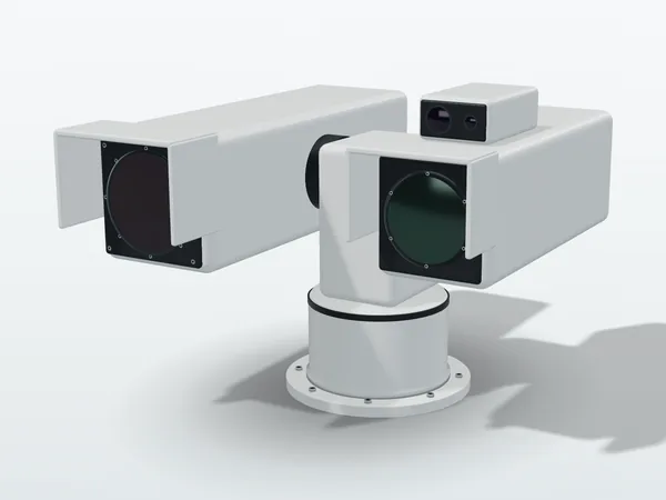
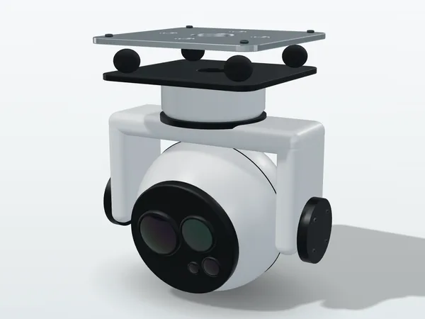
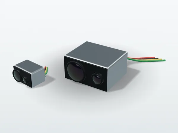
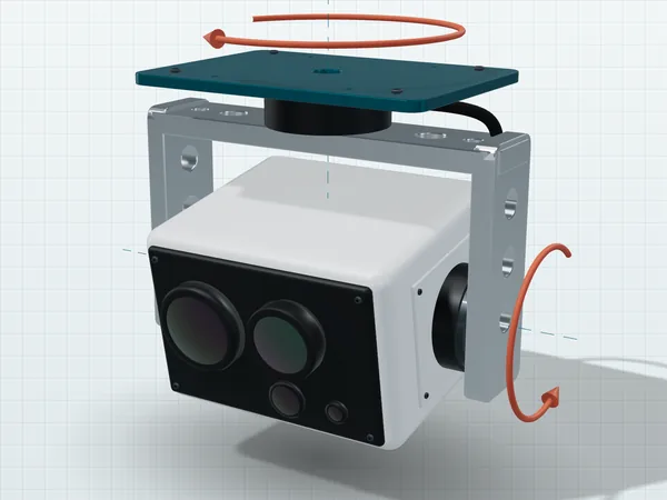
Original illustration, not a product photo. Actual appearance varies by model.

Give us the mission conditions, and we will draw the chain first

You do not need a complete specification. Tell us what must be seen, where, and where the result must go, and we will reply with a system architecture sketch, range and geolocation error budgets, and a list of interfaces to confirm first.

Further reading

Technical reference

Infrared band reference

What SWIR, MWIR and LWIR are each good at, with atmospheric windows, blackbody radiation and detector materials side by side. Read this before choosing a band.