
Passive Microwave Components
Passive Microwave Components
Coaxial adapters, fixed attenuators and terminations, selected by frequency, connector series and power and made by a partner manufacturer. For custom design and performance simulation, see passive microwave components in our services. Country of origin: Taiwan.
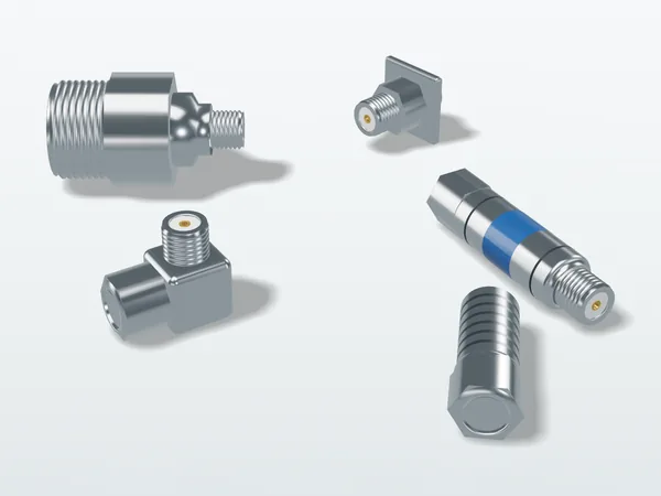
Items
| Item | Use | Key specs |
|---|---|---|
| Coaxial adapters | Transition between connector series, genders or angles | Maximum frequency, VSWR, insertion loss, impedance (50 Ω) |
| Fixed attenuators | Reduce signal level, improve impedance matching, protect instrument inputs | Attenuation (dB) and accuracy, frequency range, rated average and peak power |
| Terminations | Absorb power in a matched load, as the end of a calibration or test setup | Frequency range, VSWR, rated power |
Connector series and typical maximum frequency
| Connector series | Typical maximum frequency |
|---|---|
| N | 11 GHz (precision grade 18 GHz) |
| SMA | 18 GHz |
| 3.5 mm | 26.5 GHz |
| 2.92 mm | 40 GHz |
| 2.4 mm | 50 GHz |
| BNC | 4 GHz |
The maximum frequency depends on the connector grade and manufacturer. 3.5 mm and 2.92 mm connectors mate mechanically with SMA, but a mixed connection is limited to the lower maximum frequency.
What to include in a quote request
- Frequency range
- Connector series and gender at each end, impedance
- VSWR or return loss requirement
- Average and peak power, operating environment
- Whether a measurement report is needed (for example, S-parameters)
- Quantity and required delivery date
Related products
Original illustration, not a product photo. Actual appearance varies by model.
Specification not settled yet?
Tell us the frequency, power and connectors at each end; we will confirm the specification before quoting.