PO System TechnologyCo., Ltd. /PO Tech Studio
中文 EN

Technical Reference

Infrared band reference

Choose the wrong band, and every lens, algorithm and mechanical design after it is forced to compensate. This page puts the physics, detector options and applications of each band side by side, so that selection can be done on paper first.

1. Position in the electromagnetic spectrum

The horizontal axis is wavelength (log scale); the definitions of NIR and SWIR overlap at 0.9–1.0 µm, and the chart uses 1.0 µm as the boundary. Between 5 and 8 µm, water vapor absorbs strongly and the range is rarely used for imaging in practice, which is why there is a gap between MWIR and LWIR.

VIS NIR SWIR MWIR LWIR VLWIR H₂O absorption 0.4 0.75 1.0 1.7 2.5 3 5 8 14 20 µm Atmospheric window Atmospheric window 300 K (room temperature) peak ≈ 9.7 µm Wavelength (log scale) 0.4 0.75 1.0 1.7 2.5 3 5 8 14 20 µm VIS NIR SWIR Typically 0.9–1.7, extending to 2.5 µm MWIR Atmospheric window 3–5 µm H₂O absorption LWIR Atmospheric window 8–12 µm VLWIR 300 K (room temperature) peak ≈ 9.7 µm

By Wien's displacement law, the peak emission wavelength of an object is λpeak ≈ 2898 / T (µm·K). This formula gives the first answer to "which band should I use".

1358101420 Wavelength λ (µm) 00.51.0 9.7 µm 5.8 µm 2.9 µm MWIR LWIR 300 K 500 K 1000 K 1 3 5 8 10 14 20 0 0.5 1.0 2.9 µm 5.8 µm 9.7 µm MWIR LWIR Wavelength λ (µm) 300 K 500 K 1000 K
Blackbody emission at three temperatures, each normalized to its own peak. The hotter the object, the further the peak moves toward short wavelengths: room temperature at 300 K falls in the LWIR; 5.8 µm at 500 K falls between the MWIR and LWIR atmospheric windows; 2.9 µm at 1000 K falls between extended SWIR (2.5 µm) and MWIR (3 µm), close to the lower edge of the MWIR. This rule (λpeak ≈ 2898 / T) is the first question to ask in selection, but the peak is only a starting point: the windows on either side of the peak still collect plenty of radiation, and real selection also depends on contrast and the atmosphere.

2. Bands, detectors and applications

NETD values are typical; actual specifications vary with the model and integration time, and are meant only for order-of-magnitude judgment at the selection stage.

BandWavelengthCommon detector materialsCoolingTypical NETDApplications
NIR
near infrared
0.75 – 1.0 µm Extended sensitivity of silicon (Si) CCD/CMOS Not needed — Night-vision illumination, machine vision, biological fluorescence imaging
SWIR
shortwave infrared
0.9 – 1.7 µm
(up to 2.5 µm)
InGaAs (indium gallium arsenide) Not needed, or TEC-stabilized — Defect inspection inside silicon wafers, moisture and foreign matter detection, viewing 1064/1550 nm laser spots, haze penetration, sorting of agricultural products and recyclables
MWIR
midwave infrared
3 – 5 µm InSb (indium antimonide), HgCdTe, T2SL type-II superlattice Cooling required
(InSb about 77 K; HOT types about 110–150 K)
20 mK High-temperature process monitoring, gas detection by characteristic absorption (CO₂ 4.3 µm, CH₄ 3.3 µm), long-range observation payloads, glass and metal melting
LWIR
longwave infrared
8 – 14 µm Uncooled microbolometers (VOx/a-Si), HgCdTe Mostly not needed 40 – 60 mK
(uncooled)
Thermal imaging of objects at room temperature, power equipment and building inspection, body temperature screening, PCB hot spot analysis, thermographic non-destructive testing
VLWIR
very long-wave infrared
Above 14 µm HgCdTe, Si:As Deep cooling required — Astronomy, space remote sensing, very cold targets
Table 1: infrared bands and detectors. Cooled cameras carry far higher cost and maintenance burden than uncooled ones, and this must be weighed in selection.

3. Five criteria for selection

Answer these five questions in order, and usually only one or two bands remain.

01

What is the temperature of the object?

Use λpeak ≈ 2898 / T. Room temperature at 300 K falls at 9.7 µm (LWIR), 500 K at 5.8 µm (between the two atmospheric windows), 800 K at 3.6 µm (MWIR), and 1500 K is already at 1.9 µm (the edge of SWIR). The higher the temperature, the shorter the best band.
02

Self-emission or reflected light?

MWIR and LWIR see the thermal radiation the object emits itself and need no extra illumination; SWIR mostly sees reflected light and needs sunlight, night-sky glow or an active light source. This question directly decides whether the system needs an illumination module.

03

What does the optical path have to pass through?

Silicon becomes increasingly transparent above about 1.1 µm (above 1.15 µm it hardly absorbs at all), which is why SWIR can see inside wafers; ordinary optical glass gradually stops transmitting above about 2.5 µm, so MWIR lenses mostly use silicon or germanium, windows often use sapphire or calcium fluoride, and LWIR mostly uses germanium. Long-range atmospheric transmission in the thermal infrared relies mainly on the 3–5 µm and 8–12 µm windows; within SWIR there are also windows at about 1.0–1.35, 1.5–1.8 and 2.0–2.4 µm.

04

How small a temperature difference must be resolved?

To reliably resolve temperature differences of the 0.1 K order (for example thermographic inspection of delamination in composites), the signal usually needs to be 3 to 5 times the NETD, which is very tight for uncooled cameras (about 40–60 mK); if you only need to find overheating spots, uncooled LWIR is more than enough, and the cost can differ by an order of magnitude.

05

Do maintenance conditions allow it?

The Stirling cooler in a cooled camera is a consumable with a defined service life in operating hours, and the camera needs time to cool down at start-up. For production lines with 24-hour continuous monitoring, uncooled solutions are usually evaluated first.

Still not sure?

The difficulty in selection is usually not the table, but that your object meets several conditions at once. Describe the scenario to us, and we can do a feasibility assessment first.

Contact us →

4. Quick estimates of field of view and spatial resolution

Before requesting a quotation, use these three formulas to check whether a lens focal length is feasible.

p GSD f Working distance Focal plane array Lens Field of view IFOV p GSD f Working distance Focal plane array Lens Field of view IFOV
A pixel (pitch p) behind a lens of focal length f subtends a fixed angle IFOV = p / f; projected onto the object plane, this angle becomes the size the pixel actually covers, GSD = IFOV × distance. (Schematic, not to scale.) To see smaller defects there are only three ways: shorten the distance, lengthen the focal length, or use a smaller pixel pitch.
To calculateFormulaExample
Field of view FOV FOV = 2 · arctan( D / 2f ) Sensor width 10.88 mm, focal length 25 mm → about 24.6°
Single-pixel angle IFOV IFOV = p / f Pixel pitch 17 µm, focal length 25 mm → 0.68 mrad
Ground/workpiece resolution GSD = IFOV × distance 0.68 mrad × 10 m → about 6.8 mm per pixel
Table 2: D is the sensor size in that direction, f the lens focal length, and p the pixel pitch. For quantitative temperature measurement, the target should fill at least 3×3 pixels, or the reading will be diluted by the surrounding background.

5. Emissivity of common materials

A thermal camera measures radiation, not temperature. Set the emissivity wrong and the temperature is wrong: this is the most common source of measurement error on site.

Material surfaceEmissivity ε (approximate, LWIR)Measurement notes
Polished aluminum, stainless steel0.05 – 0.10Almost a mirror; what you measure is mostly reflected surroundings. Apply high-emissivity tape or black paint as a reference point
Oxidized or rough metal0.60 – 0.90The degree of oxidation varies widely, and may differ even within the same batch
Painted surfaces (non-metallic paint, any color)0.90 – 0.95Colors differ greatly in visible light but hardly at all in the LWIR; metallic paints with aluminum or other metal pigments are the exception, with emissivity as low as 0.3–0.6
Plastics, rubber0.90 – 0.95Thin films may be partly transparent; check the thickness
Glass0.85 – 0.95Opaque in the LWIR; you measure the surface temperature, not the interior
Human skin≈ 0.98Close to a blackbody, but strongly affected by ambient temperature and airflow
Table 3: emissivity values are approximate, consistent in magnitude with FLIR's thermography application notes; in practice, calibrate on site with real samples and a blackbody source or reference patch. For the actual errors caused by a wrong emissivity setting, see Why Do Thermal Cameras Misread Temperature? Three Pitfalls You Need to Know.

6. Quick glossary

AbbreviationFull nameDescription
NETDNoise Equivalent Temperature DifferenceNoise equivalent temperature difference. The temperature difference equivalent to the noise (signal-to-noise ratio = 1); the smaller the number, the more sensitive. To resolve reliably, a temperature difference usually needs to be 3–5 times the NETD
FPAFocal Plane ArrayFocal plane array, the sensor itself in an infrared camera
NUCNon-Uniformity CorrectionNon-uniformity correction. Compensates for differences in pixel response; key to thermal image stability
MTFModulation Transfer FunctionModulation transfer function; quantifies how well an optical system preserves contrast at each spatial frequency
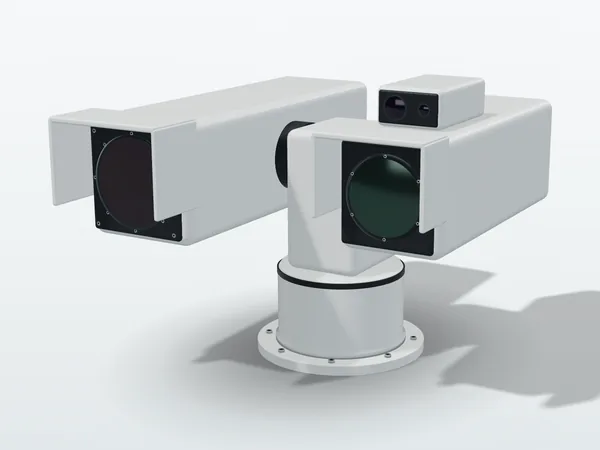
EOIRElectro-Optical / InfraredCombined visible and infrared payload, often also integrating a laser rangefinder (LRF)
LRFLaser Range FinderLaser rangefinder; boresight alignment is needed when it shares a line of sight with EO/IR
T2SLType-II SuperlatticeType-II superlattice, a new generation of detector material for MWIR/LWIR

Related products

Items related to this page that we also supply, each with specifications and selection notes.

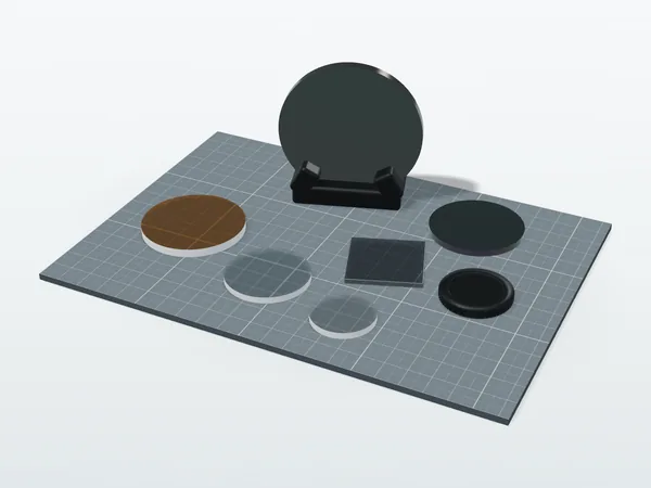
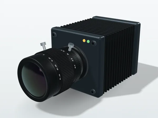
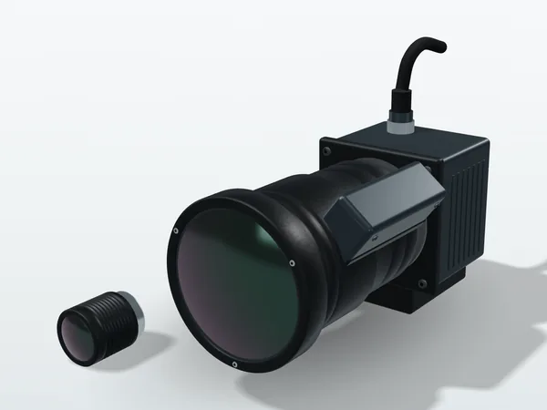
Original illustration, not a product photo. Actual appearance varies by model.

Leave the selection step to us

Infrared imaging (SWIR, MWIR, LWIR) principles consulting and advisory services: we help you confirm your choice of waveband and lens focal length, and can extend into system integration, early validation and custom test validation of camera modules.