
Test Cable Assemblies
Test Cable Assemblies
A wrong connector or wire usually shows up only in environmental testing or in the field. We select industrial or military-grade connectors and wire for the operating environment, define the pin-out and integration specification, then build the test cable. Country of origin: Taiwan.
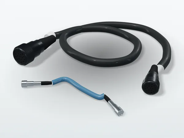
Types
| Type | Typical use |
|---|---|
| Signal test cable | Equipment functional tests; signal links between sensors and controllers |
| Power test cable | Powering the unit under test; current and voltage-drop measurement |
| RF coaxial test cable | Measurement connections for RF and microwave components and antennas |
| Adapter cable | Converting between different connector interfaces |
Conditions to confirm first
- Temperature range: ratings of the jacket and connector materials
- Vibration and shock: connector locking and cable strain relief
- Salt fog and water: connector sealing and plating
- Electromagnetic interference: shield type and grounding
- Mating cycles: durability under repeated connection on test fixtures
Connector selection and integration specifications are also offered as a service under precision mechanics and test cables; for RF components, see passive microwave components.
What to include in a quote request
- Connector models or interfaces at both ends
- Length and allowed tolerance
- Wire: conductor count, gauge, shielding and temperature rating
- Pin-out or wiring diagram
- Operating environment, and whether shipping test records (for example continuity and insulation) are needed
- Quantity and required delivery date
Related products
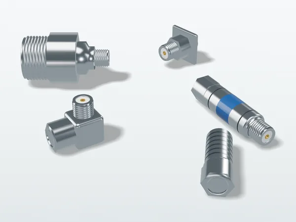
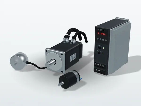
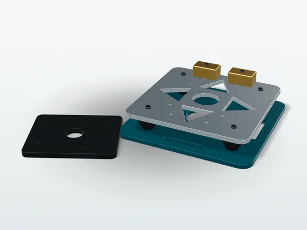
Original illustration, not a product photo. Actual appearance varies by model.
Have a wiring diagram?
Send the wiring diagram or the connector models at both ends; we will reply with a quotation and lead time.